
 대표어
대표어


권호기사보기
| 기사명 | 저자명 | 페이지 | 원문 | 기사목차 |
|---|
결과 내 검색
동의어 포함
Title Page
Contents
Nomenclature 12
Abstract 14
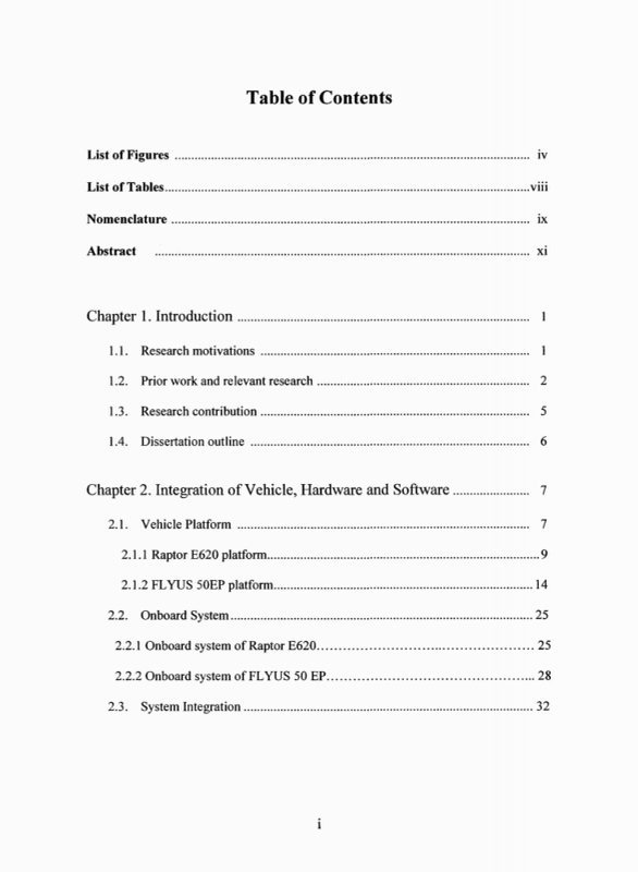
Chapter 1. Introduction 16
1.1. Research motivations 16
1.2. Prior work and relevant research 17
1.3. Research contribution 20
1.4. Dissertation outline 21
Chapter 2. Integration of Vehicle, Hardware and Software 22
2.1. Vehicle Platform 22
2.1.1. Raptor E620 platform 24
2.1.2. FLYUS 50EP platform 29
2.2. Onboard System 40
2.2.1. Onboard system of Raptor E620 40
2.2.2. Onboard system of FLYUS 50EP 43
2.3. System Integration 47
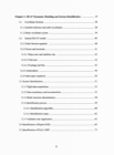
Chapter 3. RUAV Dynamics Modeling and System Identification 52
3.1 Coordinate Systems 53
3.1.1. Inertial reference and earth coordinate system 53
3.1.2. Body coordinate system 54
3.2. General RUAV model 55
3.2.1. Euler Newton equation 55
3.2.2. Forces and moments 56
3.2.2.1. Main Rotor and Stabilizer bar 58
3.2.2.2. Tail Rotor 60
3.2.2.3. Fuselage and fins 60
3.2.3. Linearization 61
3.2.4. State space equations 65
3.3. System Identification 66
3.3.1. Flight data acquisitions 68
3.3.2. Data consistency and reconstruction 70
3.3.3. Model structure determination 73
3.3.4. Identification Process 74
3.3.4.1. Identification algorithm 75
3.3.4.2. Identification steps 77
3.3.5. Validation and application 78
3.4. Identification of Raptor E620 79
3.5. Identification of Flyus 50EP 90
Chapter 4. Controller Design for RUAV 98
4.1. Control system introduction 98
4.2. Notation and terminology 101
4.3. H∞ formulation and solution 104
4.4. Attitude control design of hovering RUAV 107
4.4.1. Controller design for Raptor E620 110
4.4.2. Raptor's classical controller design 114
4.4.3. Flyus's H∞ Controller design(이미지참조) 117
4.5. Controller validation 118
4.5.1. Controller validation for Raptor E620 120
4.5.2. Controller validation for Flyus 50EP 126
4.6. Flyus's autonomous hovering test 127
Chapter 5. Conclusion 132
References 134
국문초록 141
Figure 2-1. General main - tail rotor configuration. 23
Figure 2-2. Thunder Tiger Raptor E620 RC model helicopter. 25
Figure 2-3. Collective motion of control input mechanism. 26
Figure 2-4. Lateral motion of control input mechanism. 26
Figure 2-5. Longitudinal motion of control input mechanism. 27
Figure 2-6. CCPM Manager. 28
Figure 2-7. FLYUS 50EP RC model helicopter. 29
Figure 2-8. CAD drawing of FLYUS 50EP RC. 30
Figure 2-9. The servos configuration for swash plate actuation. 32
Figure 2-10. Convention of RC controller. 32
Figure 2-11. PWM signals diagram for FLYUS 50EP. 33
Figure 2-12. Dynamic behavior of servomotor. 34
Figure 2-13. Servo outputs for collective input. 35
Figure 2-14. Servo outputs for lateral cyclic input. 36
Figure 2-15. Servos outputs for longitudinal cyclic input. 36
Figure 2-16. Servos outputs for pedal input. 37
Figure 2-17. Servos distributions. 38
Figure 2-18. Raptor E620 Onboard System. 41
Figure 2-19. Sensors mounted on the vehicle. 41
Figure 2-20. Raptor equipped with onboard system. 42
Figure 2-21. IMU MI-A3330X. 43
Figure 2-22. FCC Board. 44
Figure 2-23. FCC flow chart. 45
Figure 2-24. Side view of Flyus equipped with onboard system. 46
Figure 2-25. Flow diagram of communication system of Raptor E620. 48
Figure 2-26. Flow diagram for flight data acquisition of Flyus 50EP. 49
Figure 2-27. Flow diagram for autonomous control application. 50
Figure 2-28 Control process in ground control station. 51
Figure 3-1. Coordinate systemn for small scale helicopter system. 54
Figure 3-2. Longitudinal forces and moments. 57
Figure 3-3. Lateral forces and moments. 57
Figure 3-4. Longitudinal rotor flapping dynamics. 58
Figure 3-5. Lateral rotor flapping dynamics. 59
Figure 3-6. System identification flow chart. 67
Figure 3-7. Frequency sweep input 69
Figure 3-8. Doublet input. 70
Figure 3-9. Nondeterministic error. 72
Figure 3-10. Hover flight data acquisition. 80
Figure 3-11. Raptor's tail rotor input-output response. 81
Figure 3-12. Raptor's lateral input-output response. 81
Figure 3-13. Raptor's longitudinal input-output response. 82
Figure 3-14. Raptor's collective input and translational velocity response. 82
Figure 3-15. Raptor's roll rate response. 85
Figure 3-16. Raptor's roll angle response. 85
Figure 3-17. Raptor's pitch rate response. 86
Figure 3-18. Raptor's pitch angle response. 86
Figure 3-19. Raptor's yaw rate response. 87
Figure 3-20. Raptor's forward velocity response. 87
Figure 3-21. Raptor's lateral velocity response. 88
Figure 3-22. Raptor's axial velocity response. 88
Figure 3-23. Flyus helicopter in taking off and hovering position. 90
Figure 3-24. Flyus' longitudinal input-output response. 91
Figure 3-25. Flyus' lateral input-output response. 91
Figure 3-26. Flyus' tail rotor input-output response. 92
Figure 3-27. Flyus' collective input-output response. 92
Figure 3-28. Flyus' roll rate response. 94
Figure 3-29. Flyus' roll angle response. 94
Figure 3-30. Flyus' pitch rate response. 95
Figure 3-31. Flyus' pitch angle response. 95
Figure 3-32. Flyus' yaw rate response. 96
Figure 4-1. Control loop with plant uncertainty. 99
Figure 4-2. Trade-off between performance and stability. 100
Figure 4-3. The block diagram for H∞ control. 102
Figure 4-4. Feedback system with weighting functions. 106
Figure 4-5. Framework to design H∞ controller.(이미지참조) 109
Figure 4-6. Singular values plot of the controller. 112
Figure 4-7. Singular values plot of the plant and loop gain. 113
Figure 4-8. Maximum singular values of loop characteristic functions. 113
Figure 4-9. Root locus of longitudinal cyclic (δlon) to pitch rate (q) mode.(이미지참조) 115
Figure 4-10. Root locus of longitudinal cyclic (δlon) to pitch angle (θ) mode.(이미지참조) 116
Figure 4-11. Root locus of lateral cyclic (δlat) to pitch rate (p) mode.(이미지참조) 116
Figure 4-12. Root locus of lateral cyclic (δlat) to pitch angle (Ø) mode.(이미지참조) 117
Figure 4-13. The simulation of the MIMO control system. 119
Figure 4-14. The simulation of the classical control system. 120
Figure 4-15. Sinusoidal disturbances. 122
Figure 4-16. Step disturbances. 122
Figure 4-17. Attitude step command. 123
Figure 4-18. Attitude response without disturbances. 123
Figure 4-19. Control inputs without disturbances. 124
Figure 4-20. Attitude responses under sinusoidal disturbances. 124
Figure 4-21. Attitude response under step disturbances. 125
Figure 4-22. The attitude response under parameter variation. 125
Figure 4-23. Flight gear visualization. 126
Figure 4-24. Flyus' attitude response under parameter variation. 127
Figure 4-25. Static test with motion table. 128
Figure 4-26. Additional safety frames. 129
Figure 4-27. Static test by attaching anchors. 129
Figure 4-25. Flight test with a cable. 130
Figure 4-29. Polarity test results of attitude regulation by H∞ synthesis.(이미지참조) 131
Figure 4-30. Control response of attitude regulation by H∞ synthesis.(이미지참조) 131
*표시는 필수 입력사항입니다.
| 전화번호 |
|---|
| 기사명 | 저자명 | 페이지 | 원문 | 기사목차 |
|---|
| 번호 | 발행일자 | 권호명 | 제본정보 | 자료실 | 원문 | 신청 페이지 |
|---|
도서위치안내: / 서가번호:

우편복사 목록담기를 완료하였습니다.
*표시는 필수 입력사항입니다.
저장 되었습니다.
